What is a JT file?
JT (Jupiter Tessellation) is an efficient, industry-focused and flexible ISO-standardized 3D data format developed by Siemens PLM Software. Mechanical CAD domains of Aerospace, automotive industry, and Heavy Equipment use JT as their most leading 3D visualization format.
JT format is a scene graph that supports the attributes and nodes that are CAD specific. Sophisticated compression techniques are used to store facet data (triangles). This format is structured to support visual attributes, product and manufacturing information (PMI), and Metadata. There is a good support for asynchronous streaming of content. In heavy mechanical industry, professionals use JT file in their CAD solutions and product lifecycle management (PLM) software programs to examine the geometry of complicated goods.
As JT supports nearly all important 3D CAD formats its assembly can deal with a variety of combination which is known as “multi-CAD”. This multi-CAD assembly is always well managed and up-to-date because synchronization among native CAD product description files with their associated JT files takes place automatically. JT files are originally lightweight, so considered to be suitable for internet collaborations. Companies Collaborate through sending 3D visualizations over the media much more easily as compared to “heavy" original CAD files. In addition, JT files ensures many security feature that make intellectual property sharing more secure.
Brief History of JT File Format
Engineering Animation, Inc. and Hewlett Packard were the original designers of JT, who developed that format as the Direct Model toolkit. After EAI was acquired by UGS Corp. JT became a part of UGS’s suite. Early in 2007, UGS announced JT as their master 3D format. In the same year, Siemens AG purchased UGS and turn out to be Siemens PLM Software. Siemens uses JT as the common interoperability format and data archival format. In 2009, ISO accepted JT specification for publication as an ISO Publicly Available Specification (PAS).In the middle of 2010, ProSTEP iViP announced that at industrial level, JT and STEP AP 242 XML can be used together to achieve the maximum advantage in data exchange scenarios. In 2012, JT has been officially declared as an ISO-standardized (ISO 14306:2012 (ISO JT V1)) 3D visualization format.
JT File Format
All objects in the JT format are represented through an object identifier and references among objects are handled through referenced object’s identifier. The integrity of these object references can be maintained through pointers unswizzling/swizzling.
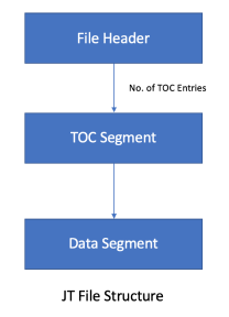
A JT file is arranged as a series of blocks and Header block is always the first block of data in the file. A series of data segment and a TOC segment immediately follow the header block. The one Data segment (6 LSG Segment) possesses a reference compliant JT file always exists. TOC Segment contains the location information of all other Data Segments of that file.

File Header
File Header is the first block in the JT file’s data hierarchy. Versioning information and TOC location information is enclosed within the header which facilitates loaders in file reading. The file header contents are arranged as follows.
TOC Segment
The TOC Segment must exist within a file and contains identification and location information of all other data segments. The actual location of the TOC Segment is specified by the TOC Offset field of the file header. Each individually addressable Data Segment is represented by TOC entry in a TOC segment.
Data Segment
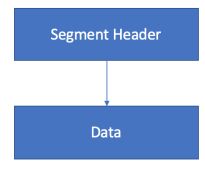
JT file defines all stored data within a Data Segment. Some Data Segment can compress all the data bytes of information remained within the segment. Data segments have the following structure:

Following table describes different types of data segments:
| Name | Description |
|---|---|
| LSG segment | Comprises a collection of objects linked through directed references to form LSG (directed acyclic graph structure) |
| Shape LOD segment | contains the defining data for the geometric shapes(e.g. vertices, normals, polygons, etc) |
| JT B-Rep Segment | Having element for the data to represent the precise geometric boundary for an individual portion in JT B-Rep format. |
| XT B-Rep segment | Having element for the data to represent the precise geometric boundary for an individual portion in boundary representation format |
| Wireframe segment | The data represents precise 3D wireframe for a particular portion is defined by an element contained in this segment. |
| Meta Data segment | Allows to store metadata in distinct addressable segments. |
| JT ULP segment | Having element for the data to represent the semi-precise geometric boundary for an individual portion in JT ULP format. |
| JT LWPA segment | Contains an element define analytic data for a particular part. LWPA encloses the analytic surfaces collection in the b-rep definition of the part. |
Compression
Transmission and storage requirements of 3D models are more demanding, so JT files may take the benefit of compression. A JT data model may be composed of different files using different compression technique but the compression process is transparent to JT data user.
So far, JT Open Toolkit (as a standard) and advanced compression are two compression techniques used by JT files. JT Open Toolkit employs an easy, lossless compression algorithm, while the advanced compression employs a more refined, domain-specific compression technique leads to lossy geometry compression. Client applications prefer advanced compression rather than using standard compression, as advanced compression yields fairly high compression ratios. Backward compatibility with ordinary JT file viewing applications are maintained through the provision of standard compression. The compression form must be compatible with the JT file format version which can be seen when a JT file opens using text editor and enclosed within ASCII header information.